Digital Communication Systems
Digital communication systems transmit measured information as binary. This means that instrument readings need to be converted to binary either inside the device or via a PROFIBUS IO block. The converted binary string is sent down the cables as high-frequency switching wave-forms. Analogue systems, however, are continuous and do not convert the information, the analogue value is transmitted as a correspondingly varying voltage/current.
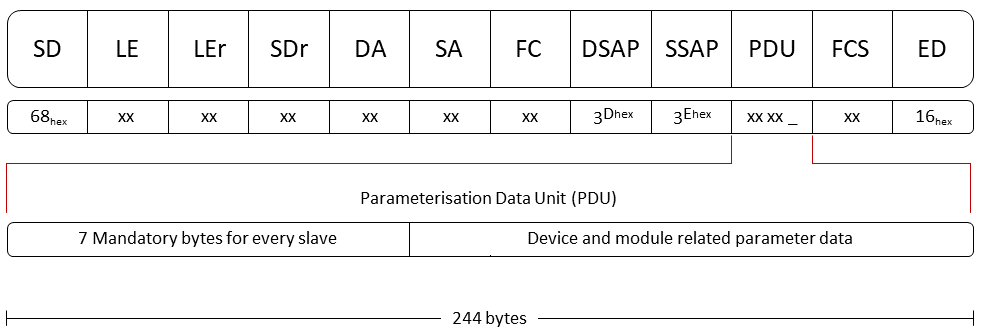
The measured information mentioned above is exchanged by grouping bits/bytes of binary together into messages or telegrams that pass between stations. The messages have a fixed/known notation that all the devices know how to decode according to the protocol rule, for example:

The PROFIBUS Family
The PROFIBUS protocol family consists of three separate but interoperable standards:
PROFIBUS FMS – Fieldbus Message Specification
High-end, application-level communications. The User at cell or controller level. Obsolete and no longer supported.
PROFIBUS DP – Decentralised Periphery
Cost-effective, high speed, simple field-level communications. About 90% of current PROFIBUS applications are DP.
PROFIBUS PA – Process Automation
Developed specifically for the process industry, a very cost-effective two-wire connection carrying both power and data. Particularly cost-effective for hazardous environments (intrinsically safe protection).

Digital Systems Physics
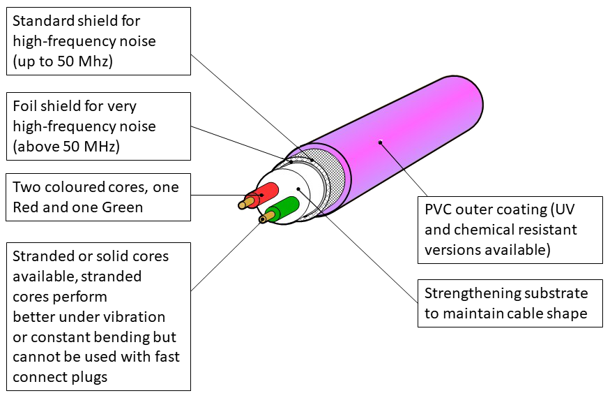
If the impedance of the cable suddenly changes at some point along with it, there is a reflection of a portion of the original signal back towards the transmitter, which will disrupt further messages traveling down the cable. The type of cable is important, the impedance must match the frequencies the signals vary by on the cable. Remember: Fieldbus cable is not just a wire.
Where ever electric charge is flowing, we will find both an electrical and a magnetic field. These fields can cause charge to flow in nearby conductive objects, this is known as coupling or pickup. If these fields affect nearby communications cable signals, we call the effect interference or noise. Electrostatic interference is reduced as the distance between cables is increased.
What are some advantages of fieldbuses?
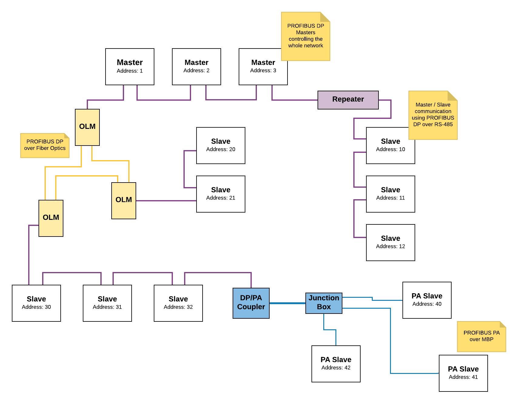
PROFIBUS Network Layout Example

