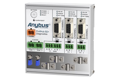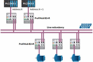
Two galvanically isolated transparent repeaters (three segments)
The ProfiHub B2+ is equipped with two galvanically isolated transparent repeaters (offering three segments). Each segment can handle 31 devices and a cable length equal to the main bus. To save costs on plugs and offer flexibility, the repeater contains screw terminals as well as DB9 connectors. Termination for each segment is on-board and switchable.
If bus redundancy is enabled, two segments will form a redundant pair which is completely compatible with the ABB RLM01. An alarm contact is linked to events based on the status of the power supply and the bus redundancy status.
Product Information
• Barrier for non-galvanic isolated equipment

Dimensions and weight
| L x H x D: | 109 x 113 x 35 mm (excluding DIN-rail and plug-able screw connectors). |
| Weight: |
328 g (excluding plug-able screw connectors, cable brackets and packing material).
|
| Mounting DIN-rail type | 35mm × 7,5mm (EN 50022, BS 5584, DIN 46277-3) |
Ambient conditions
| Operating temperature range |
-25 to +70o Celsius -13 to +158o Fahrenheit
|
| Isolation class | IP 20 (IEC/EN 60529, DIN 40050) |
Protocol specification
| Supported Protocols | DP-V0, DP- V1, DP-V2, FDL, MPI, FMS, PROFIsafe, PROFIdrive and any other FDL based protocol. | ||||||||||||||||||||||||||||||||||||||||
| Transmission speed | 9.6 kbps to 12 Mbps (including 45.45 kbps) | ||||||||||||||||||||||||||||||||||||||||
| Transmission speed detection | Auto detect | ||||||||||||||||||||||||||||||||||||||||
| Transmission speed detection time | < 10 s detection and 50 s baudrate switchover time. | ||||||||||||||||||||||||||||||||||||||||
| Transmission speed switch |
For older ProfiHubs refer to paragraph 2.10.1 |
||||||||||||||||||||||||||||||||||||||||
| Data delay time |
At baudrate Normal mode Robust mode 9.6 – 500 kbps 2.8 Tbit 13.8 Tbit 1.5 Mbps 3.2 Tbit 14.2 Tbit 3 Mbps 3.9 Tbit 14.5 Tbit 6 Mbps 4.6 Tbit 15.6 Tbit 12 Mbps 6.4 Tbit 17.4 Tbit |
||||||||||||||||||||||||||||||||||||||||
| Deviation | 2 bit times (over the complete message) for received messages is allowed and is corrected to nominal speed when transmitted. |
PROFIBUS Diagnostics Device specifications
| Supported Protocol | DP-V0 |
| Ident Number | 6971 |
| GSD filename | PROC6971.gsd |
| Bus address | 0-126 (software address only, set by software, default 126) |
| Transmission speed | 9.6 kbps to 12 Mbps (including 45.45 kbps) |
| Transmission speed detection | Auto Detect |
| Maximum transferrable data | 85 bytes input and 5 bytes output |
PROFIBUS cable specifications
| Cable lengths |
1200 m at 9.6 kbps to 93.75 kbps 1000 m at 187.5 kbps 400 m at 500 kbps 200 m at 1.5 Mbps 100 m at 3 Mbps to 12 Mbps |
| Cable thickness | 10 mm (when the ground rail is used) |
| Wire diameter (for the screw terminals) | < 2.5 mm2 |
| Wire type | Stranded or solid core |
| Number of devices | Maximum 31 per Channel (including ProfiHubs, OLMs, Laptops/PCs, etc.) |
| Termination |
Integrated and switchable. Powered according to IEC 61158 (390/220/390 Ohms) – All Channels (default on) – Main-Channel (default off) |
| Redundancy | Yes (Channel 1 and 2) |
| Cascading depth | No limit (only limited by busparameter of the master) |
| Cascading units |
With standard busparameters: At baudrate Normal mode[units] Robust mode[units] 9.6 kbps 6 6 1 19.2 kbps 6 6 1 45.45 kbps 39 39 8 93.75 kbps 6 6 1 187.5 kbps 6 6 1 500 kbps 16 16 3 1.5 Mbps 20 20 5 3 Mbps 17 17 5 6 Mbps 13 13 4 12 Mbps 13 13 5 |
Power supply specifications
| Power supply operating voltage | 12 to 24 VDC |
| Power supply absolute max rated voltage | 9 to 31 VDC |
| Redundant power supply | Yes |
| Current consumption | 125 mA at 24 V power supply (all Channels fully loaded) |
| Power dissipation | Max. 3.3 W |
| Reverse polarity protection | Yes |
| Cable thickness | 10 mm (when the ground rail is used) |
| Wire diameter | < 2.5 mm2 |
Alarm contact
| Voltage | Max. 24 VDC |
| Current | Max. 0.5 A |
Connector Lay-out
| 2x Power supply POW 1 and POW 2 |
Plug-able screw connector, pitch 5,08 mm Pin + : 12 to 24 VDC Pin – : 0 V Screw: Shield |
| Alarm Contact |
Plug-able screw connector, pitch 5,08 mm Pin 1: relay contact (potential-free) |
| PROFIBUS screw terminals Main Channel and Channel 1 to 2 |
Plug-able screw terminal, pitch 3,81 mm Pin A: PROFIBUS A (green wire) Pin B: PROFIBUS B (red wire) Pin I : Indirect shield |
| PROFIBUS DB9 Main Channel |
D Sub connector, 9 contacts (PROFIBUS specification) Pin 1: N.C. Shield is connected internally to the DIN-rail Pin I is connected internally with 10nF/1MOhm to shield. |
Standard and approvals
| CE |
EMC Directive 2014/30/EU, class B Digital Device RoHs Directive 2011/65/EU
|
| FCC | 47 CFR 15, Unintentional Radiator, class B Digital Device. |
| UL |
Report reference: E365044-A1-UL Standards for safety: UL 60950-1, Information Technology Equipment – Safety – Part 1 General Requirements CAN/CSA C22.2 No. 60950-1-07, Information Technology Equipment – Safety – Part 1: General Requirements |
| Order Codes | 17210R |
| Included Components | Anybus ProfiHub B2+ |
| Warranty | 1 year |
Book your product
We are fully committed to providing our customers with the very best products and customer service. We believe in going the extra mile to ensure that each customer is satisfied with our products and solutions. We have the experience and the reputation in the field to deliver the products customers need to expedite their projects and assure quality every step of the way.

Our expertise lies in establishing, maintaining, and leveraging plant data for business benefit. Through our innovative solutions, we work alongside you to streamline processes, enhance efficiency, and reduce costly downtime.
CONTACT US
Main: +27 (11) 548 9960
Sales: +27 (11) 548 9970
SOCIAL MEDIA
Copyright @2025 Industrial Data Xchange.
All rights reserved.
